
Since our last blog post, we’ve been meeting weekly to design, programming, build, and discuss logistics of our project to build a robot for virtual members to navigate around the lab. The design went through a number of iterations before we landed on a design we liked. The first design we made had a triangular shape similar to Lawton’s FTC robot, and two sets of linear slides with a tablet and camera in between (not shown). It also had a heavy mecanum drive base to ensure extending the slides didn’t cause the center of gravity to move up too much. It was a promising start, but had a number of improvements before we could begin building.
With version 2, we kept with the same frame, however changed the drivetrain and lift based on feedback we got from other members and mentors. We determined mecanum wheels were not worth the trouble. Because the video camera will be fixed to pointing forwards, rarely will drivers need to move sideways, and if they did it could pose a danger to those outside of the camera’s view. Instead, we used two drive wheels with omni wheels on the edges to keep the robot upright. This ensures the center of gravity is fairly centered, and the robot turns from its center. We also moved to a single linear slide to reduce weight and cost. Finally, we added an LCD screen to the front, which will be a 64×32 LED matrix to display the user’s name, or any other relevant information. This is in addition to the same screen and camera setup we had on the previous version.
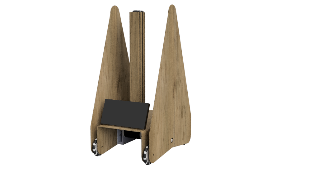
On version 3, we revised the frame to better match the structure of the components. The triangle shape was good for having two slides, however with just one it didn’t serve a purpose. Instead, we made the frame much closer to the ground, with the slide extending above it. We also added bumpers similar to FRC to protect members, walls, and the robot. This design seemed to have consensus among the team to be the best, so we proceeded to now figure out manufacturing.
We designed one final design, version 4, which keeps all of the design aspects of version 3, but much easier to fabricate. It has notches in the wood to fit components together, angle brackets to attach components together, and fasteners. We also added some features like a limit switch by the door to detect when it is closed, and the motor to lift the slide.
On the programming side, we have also seen success in the remote control part of the project. All the way from Mexico, 3700 miles away, one of our remote members, Brian, was able to successfully light up LEDs that are in Anchorage.
Here is the video that shows this:
During our last zoom, we tested the remote control capabilities with other members as well, and they all successfully lighted up the LEDs. We have distant members from Fairbanks and even Mexico… but even during the times of the pandemic, we strive to be connected as a team.